
TRS-80 Model I RS-232 Interface Re-Creation
I am releasing my first hardware product, a recreation of the Radio Shack 26-1145 RS-232 interface board for the TRS-80 Model I microcomputer.

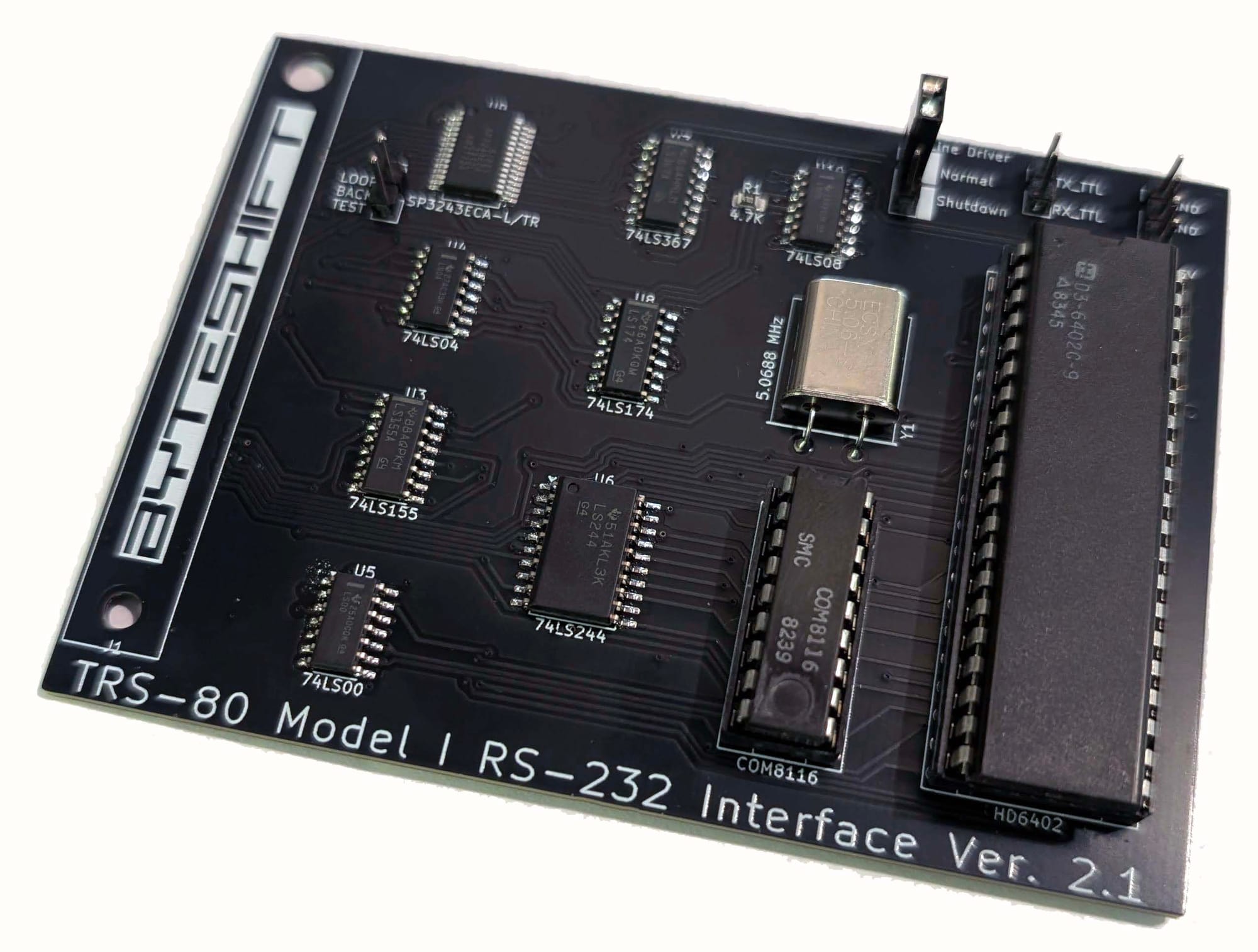
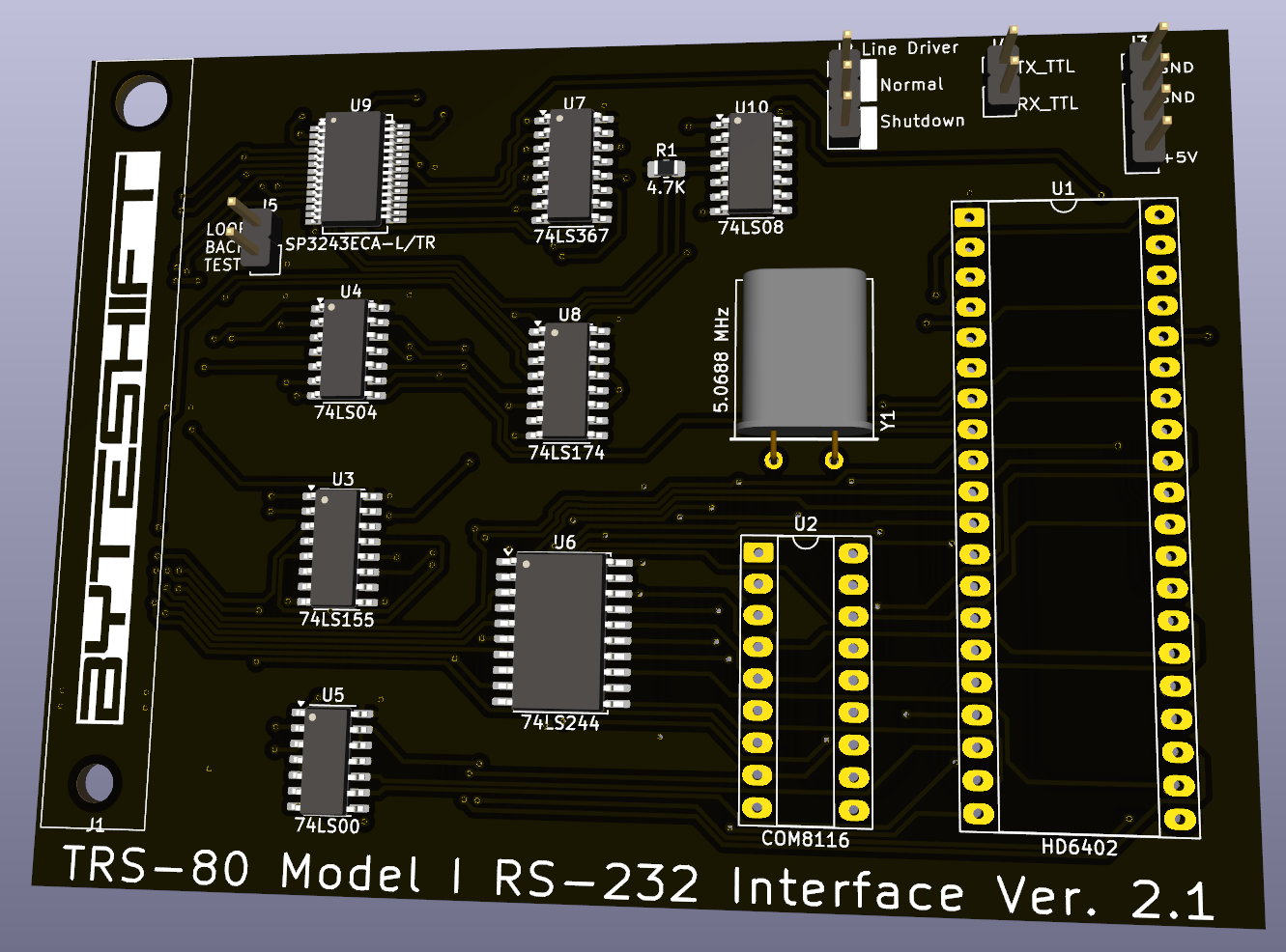
Recently, I needed serial connectivity for my TRS-80 Model I, but the original Radio Shack "TRS-80 RS-232-C Interface", catalog number 26-1145, is extremely hard to find these days. So, armed with the manual and schematics, I proceeded to design my own version, using (more) modern components, to simplify the design and lower the cost. Now that my design has been through a few revisions, and has been well-tested, I offer my creation to you.
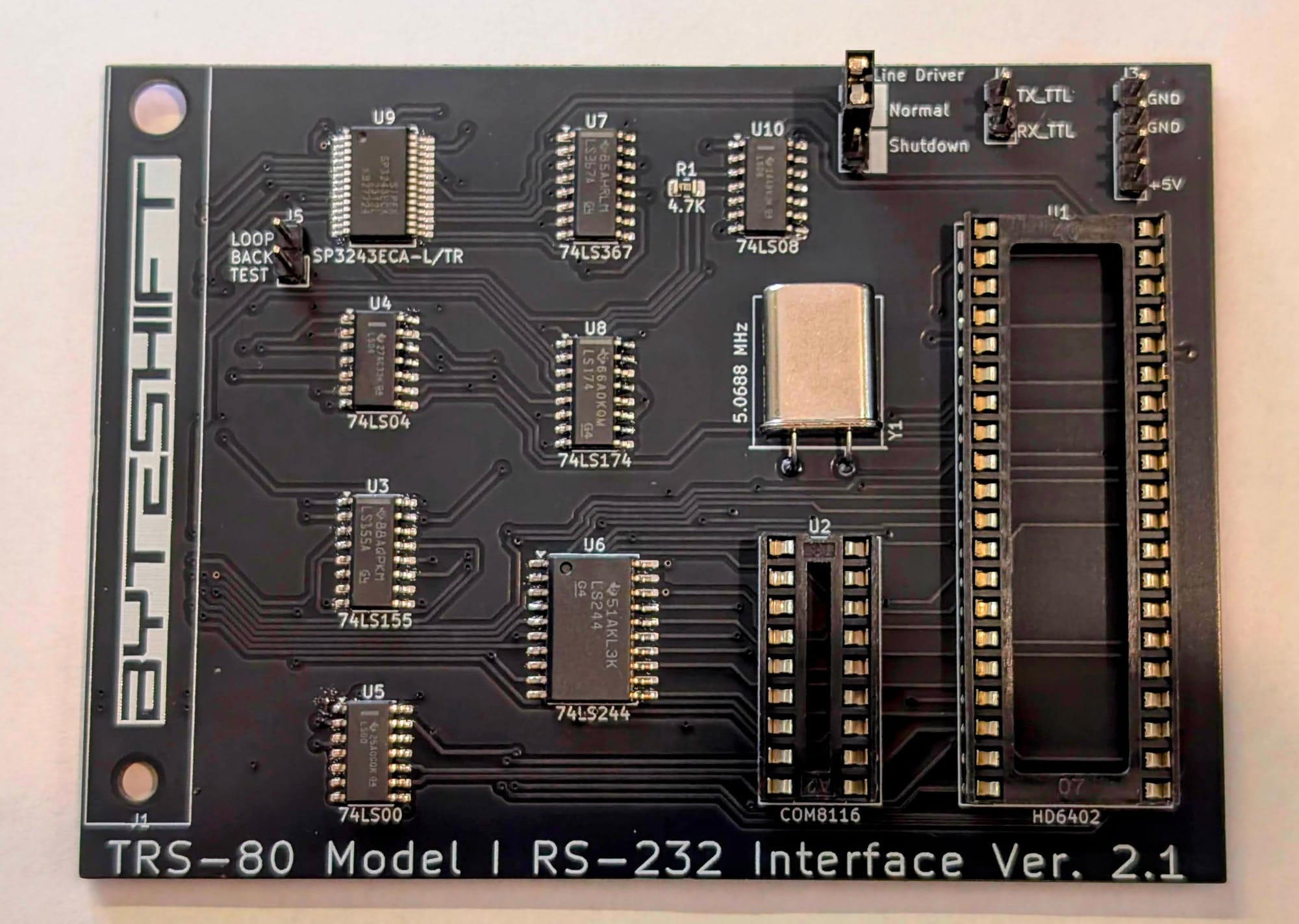
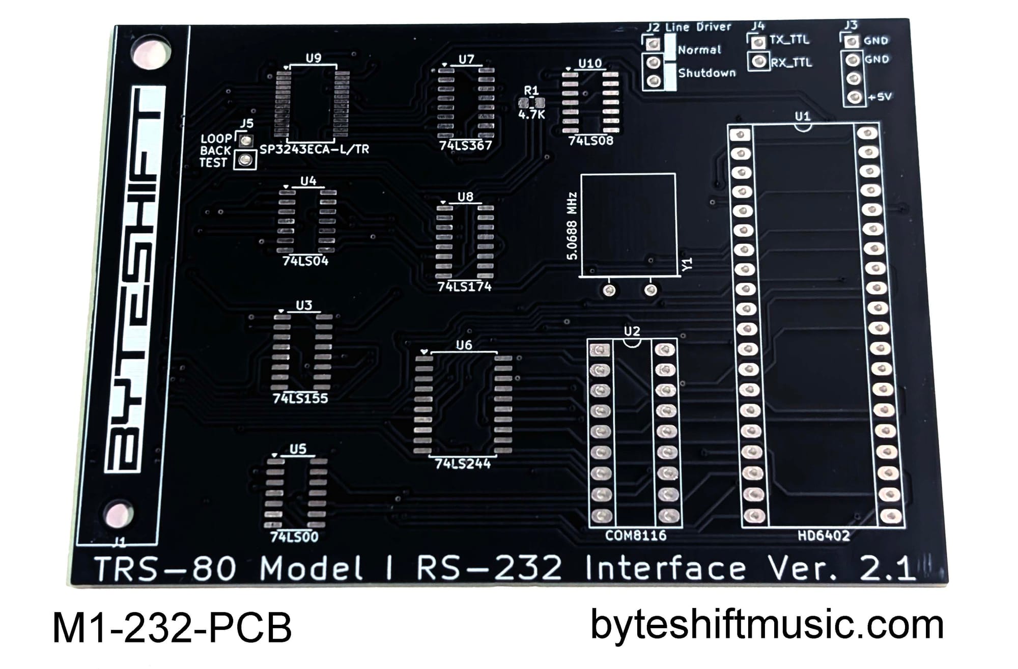
My design replicates the operation of the original board, ensuring compatibility with existing Model I software. However, hardware-wise, there are a few differences:
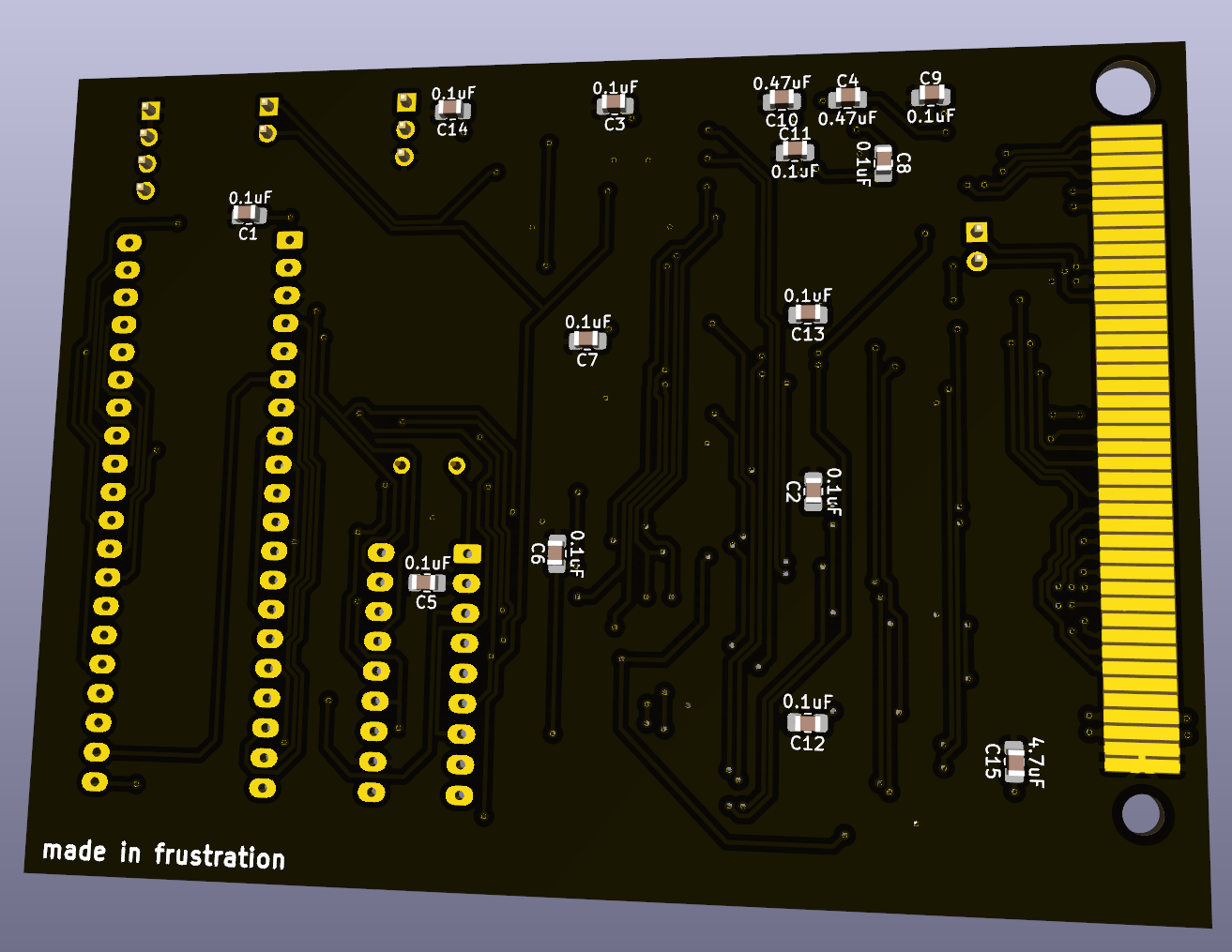
- SMT components are used wherever possible, to minimize cost
- Sense switch (DIP switch configuration) functionality has been removed. The interface must be configured via software before use.
- The TERM/COMM switch has been removed. The unit is configured in TERM (DTE) mode, and an external null-modem adapter should be used if operation as a DCE device is required.
- UART and baud rate generator IC selection eliminates the need for +12v/-12v/-5v supply rails, simplifying the design and lowering parts count.
Features:
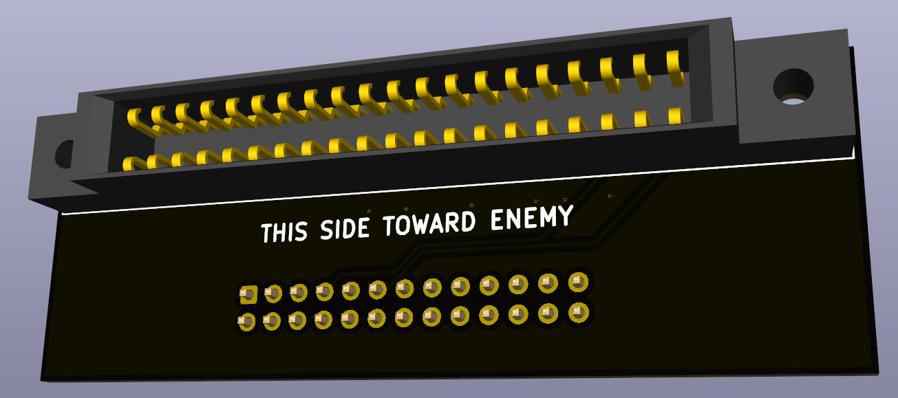
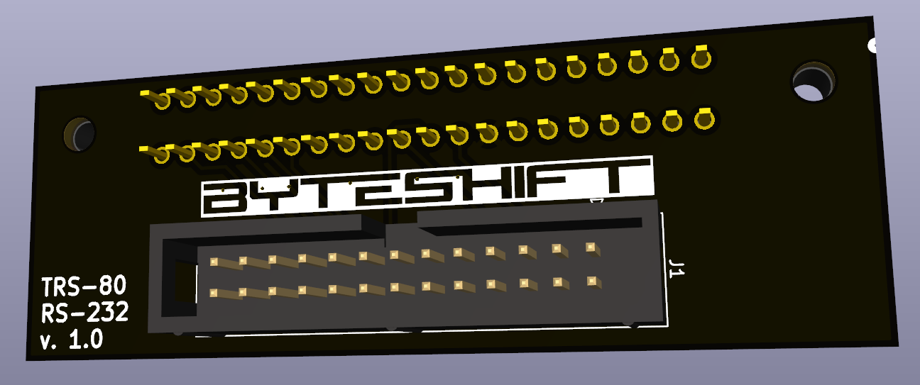
- Identical form factor and mounting method to the original 26-1145 board
- baud rate: programmable 50 to 19200
- word length: 5, 6, 7, or 8 bits
- stop bits: 1/2 (or 1/1.5 with 5 bit word length)
- parity: Odd, even, none
- Jumperable RS-232 loopback header for easy testing
- Breakout headers for TTL-level TX, TTL-level RX, +5V, and GND for adding an internal ESP8266 running WiFiModem firmware (or similar hardware)
- Jumperable headers for transceiver shutdown when using internal TTL-level TX/RX headers
- Open Source: Gerbers, schematics, BOM, and KiCAD source files available on Github
Requirements for use:
- TRS-80 Model I, Level II, with at least 16k RAM
- Expansion Interface
Ordering Information:
I offer the board in several configurations, ranging from bare PCB to turnkey assembled and tested. I also offer an adapter board for the Expansion Interface's front card edge to DB-25, using a standard PC parallel port pigtail. Please specify the SKU when ordering. Prices are in USD, and include domestic ground shipping. Shipping costs for non-US destinations can be negotiated.
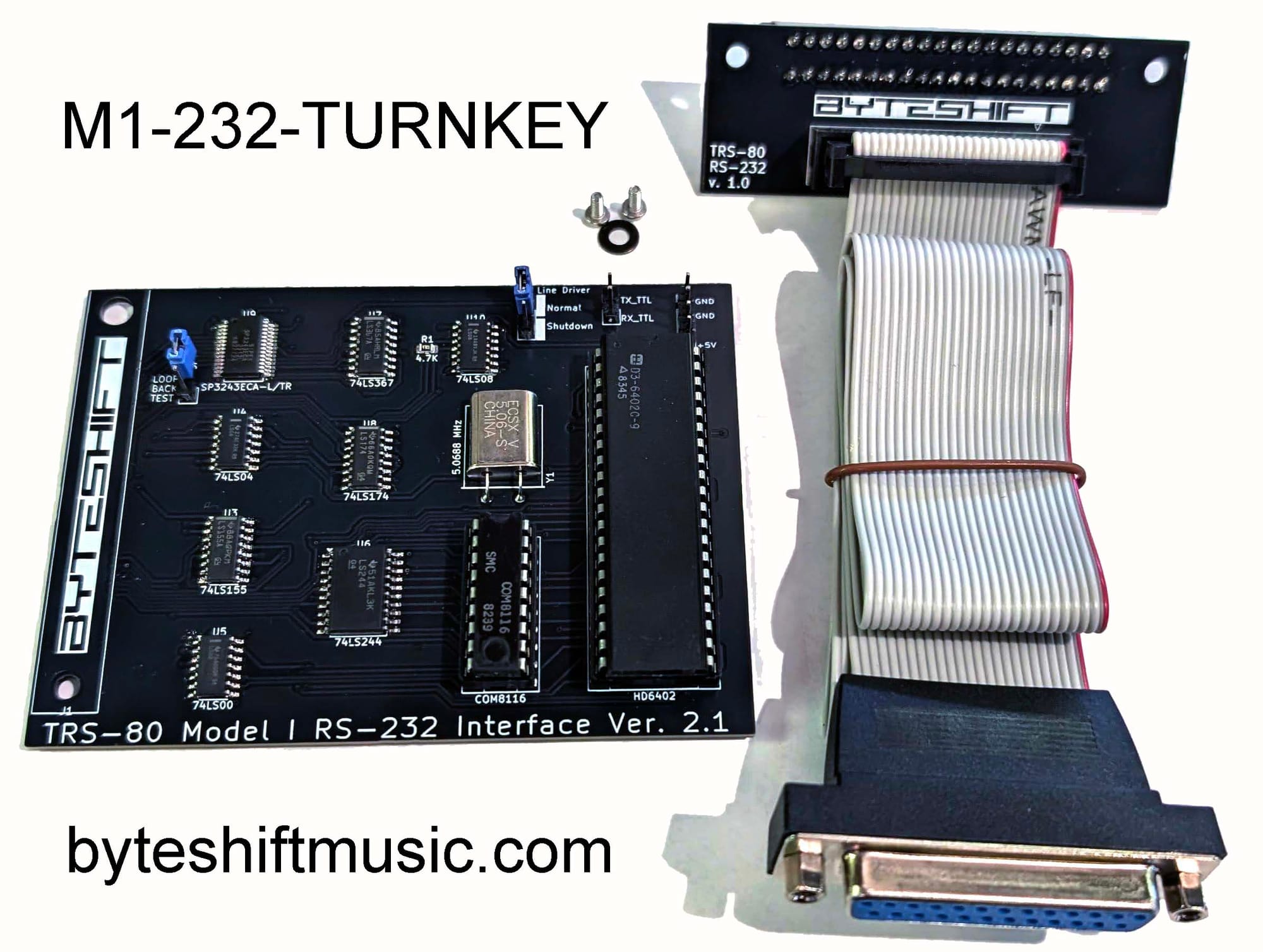
M1-232-TURNKEY - $105 USD
Complete turnkey solution - save $10
What you get:
- TRS-80 Model I RS-232 Interface Ver. 2.1, assembled & tested
- #2-56 mounting screws (qty. 2) and washer (qty. 1)
- jumpers for transceiver shutdown/loopback testing (qty. 2)
- Card-edge adapter board, assembled & tested
- 16 inch IDC26 to DB25 female pigtail cable
- free shipping within the continental United States
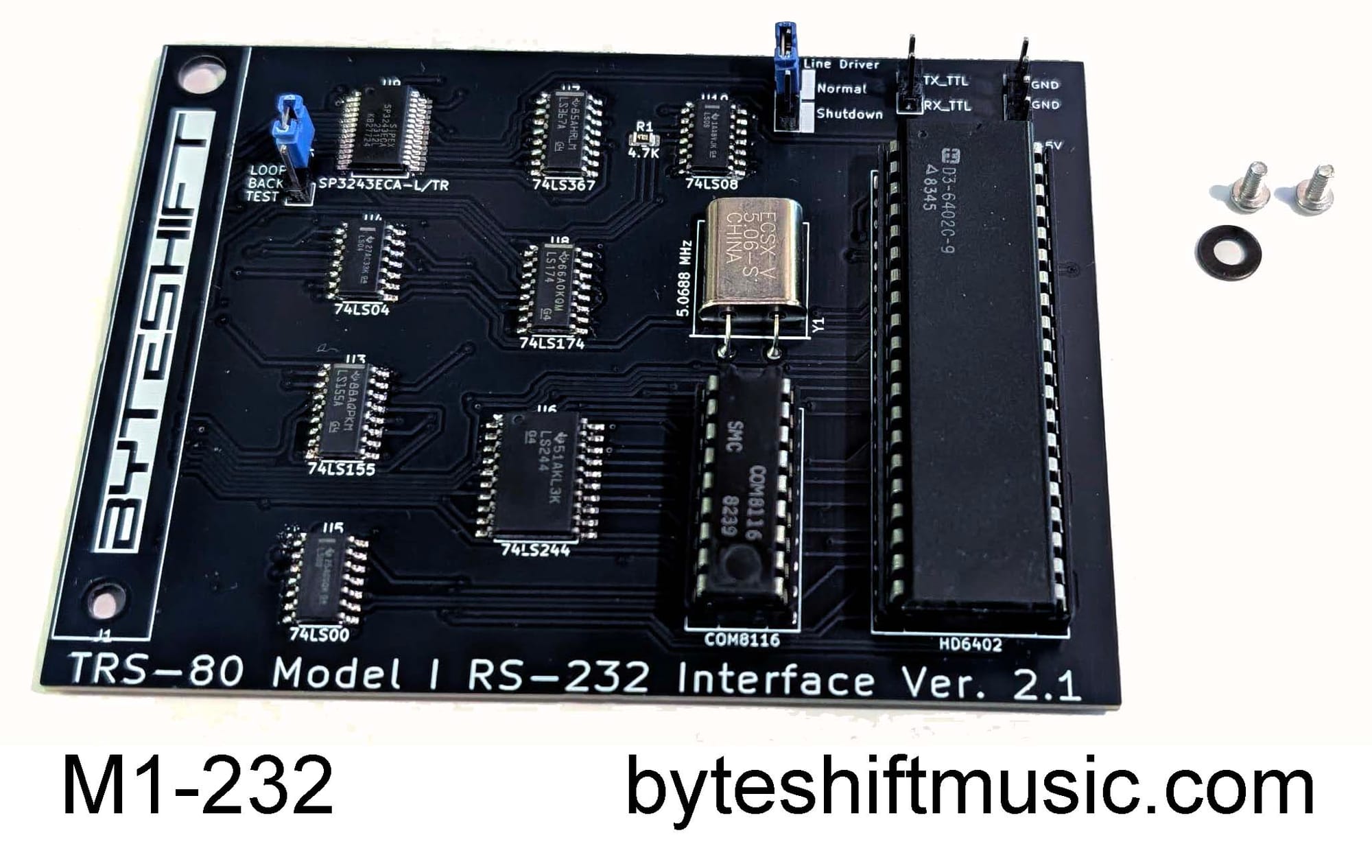
M1-232 - $80 USD
For use when you already have a card-edge to DB25 cable, and just need the interface board
What you get:
- TRS-80 Model I RS-232 Interface Ver. 2.1, assembled & tested
- #2-56 mounting screws (qty. 2) and washer (qty. 1)
- jumpers for transceiver shutdown/loopback testing (qty. 2)
- free shipping within the continental United States
M1-232-PCB - $15 USD
Bare PCB only - For use when you would like to provide your own components and build your own interface
What you get:
- TRS-80 Model I RS-232 Interface Ver. 2.1 PCB only (unpopulated)
- free shipping within the continental United States
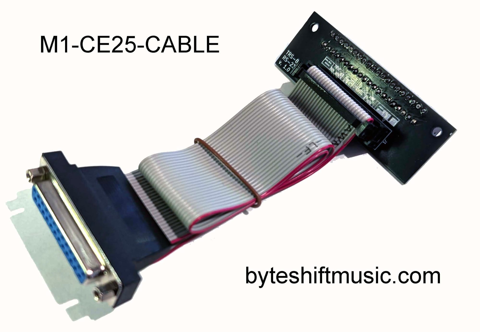
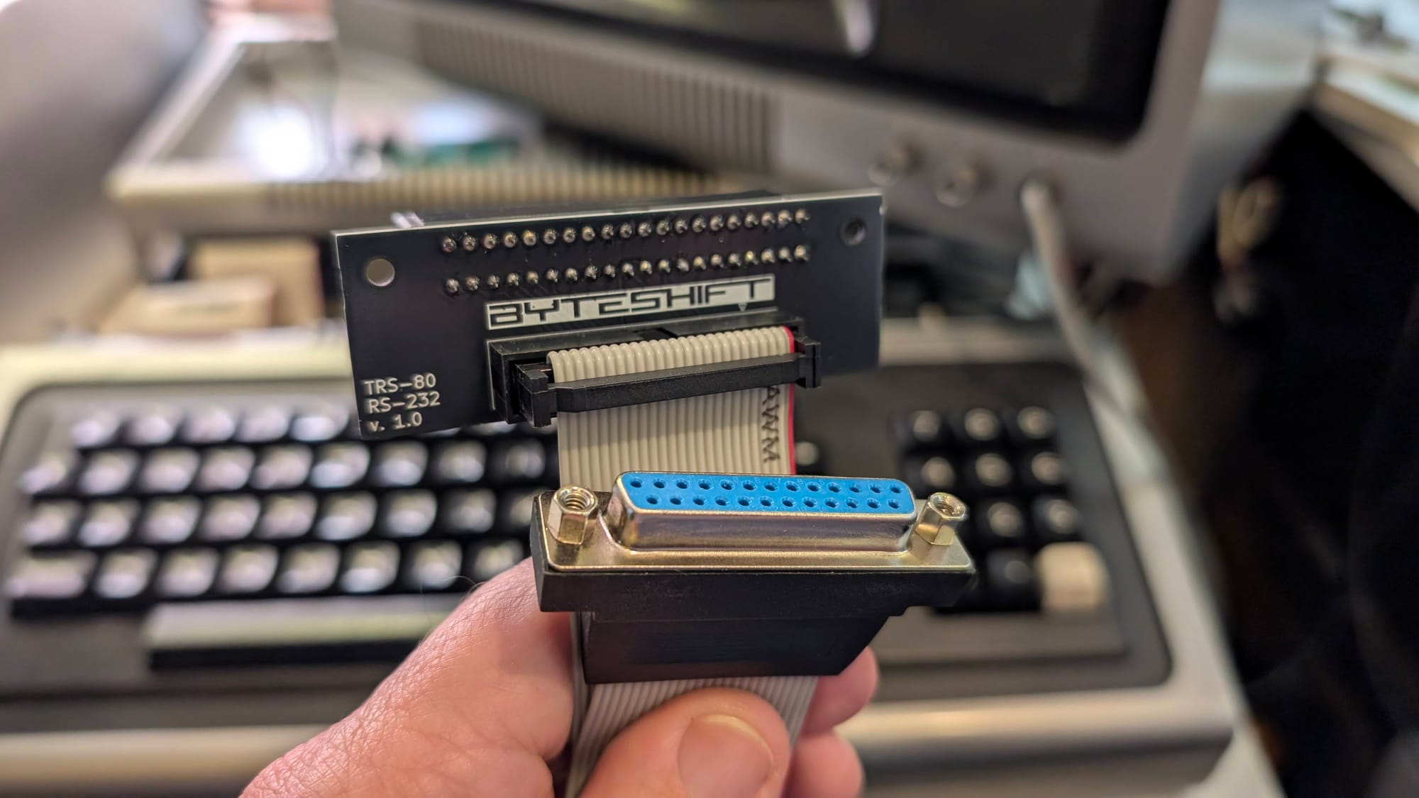
M1-CE25-CABLE - $35 USD
Expansion Interface card-edge to DB25 female adapter cable - 16 inch
What you get:
- M1-CE25 40 pin card edge to IDC25 adapter board, assembled and tested
- 16 inch IDC26 to DB25 female cable
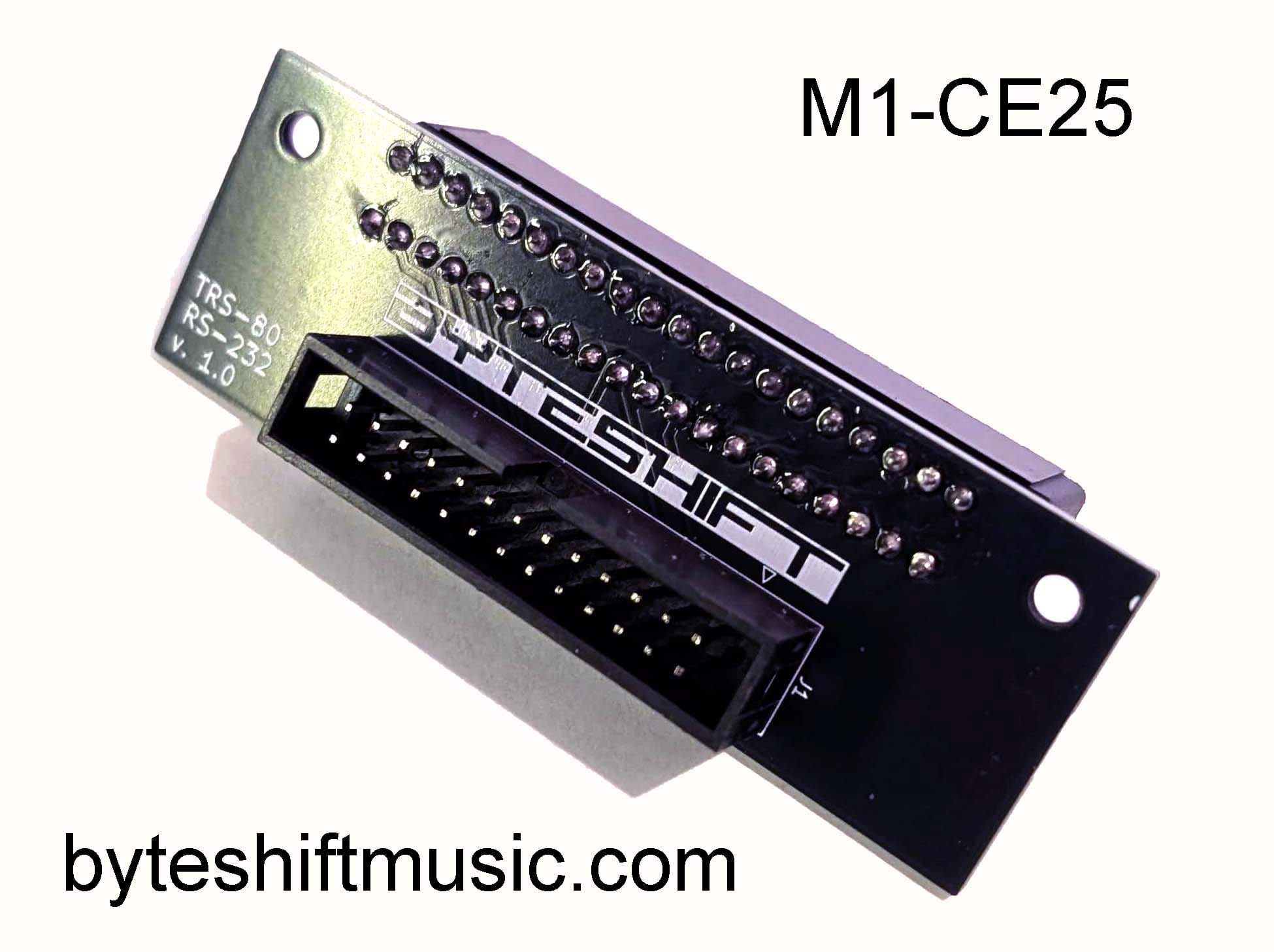
M1-CE25 - $30 USD
Expansion Interface card-edge to IDC26 adapter board, assembled and tested. Provide your own IDC26 to DB25 cable: Uses a standard PC parallel port pigtail (Startech.com PLATE25F16 or equivalent)
What you get:
- M1-CE25 40 pin card edge to IDC26 adapter board, assembled and tested (supply your own DB25 pigtail)
How to Order
I accept payment via PayPal.
Please click here to be redirected to a Google Form for ordering. I will be in contact with you shortly for confirmation, and with PayPal instructions. Please be aware that I have limited stock of these units, and that they are hand-built, so it's possible that delivery could take a while. You will not be required to make payment until your merchandise is ready to ship.
Documentation and Support
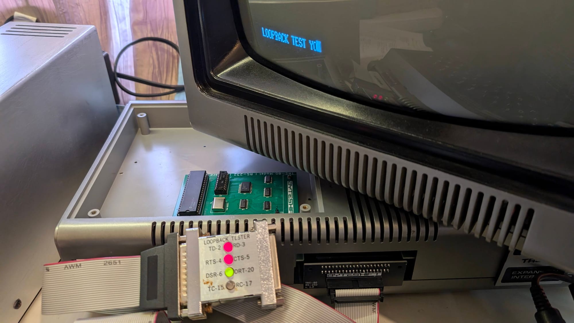
For normal operation as a replacement for the 26-1145 board, place the jumper on J2 (Line driver) in the 'Normal' position. J5 (Loopback test) should be unjumpered.
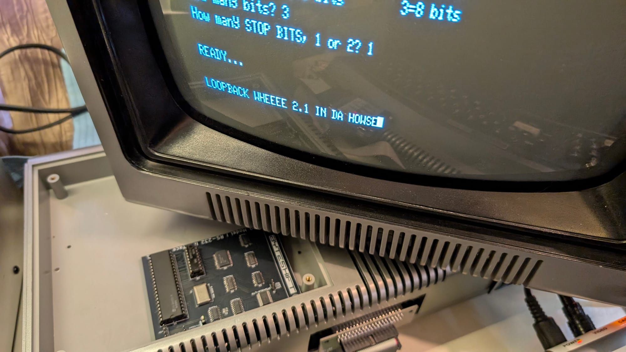
For testing without a serial cable connected to the Expansion Interface's card edge, place a jumper across J5 (Loopback test) and execute my diagnostics software, or terminal software of your choice. Any characters transmitted will be echoed back, and received. Remove the jumper from J5 when tests are complete.
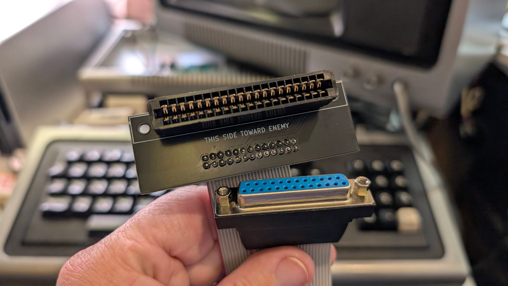
To install in the Expansion Interface (EI), first ensure that the power is disconnected. Then, remove the four phillips screws from the expansion area cover on the top left of the EI. Remove the cover, exposing the 42-pin expansion connector. If your expansion connector has screws/washers installed already, then remove them. Place the BYTESHIFT RS-232 Interface on the connector, with the row of silver fingers facing downwards. One mounting hole is larger than the other – ensure that these holes match the screw positions of the connector. Then, reinstall the screws/washers (or use the ones supplied with the kit), making sure to install a washer under the screw of the larger mounting hole. After this, you may proceed to test the unit. You may also reference the instruction manual for the original 26-1145 board, which is available for download here:
I have also written a BASIC diagnostics program capable of setting RS-232 parameters, setting and monitoring status lines, and (slowly) sending/receiving characters:
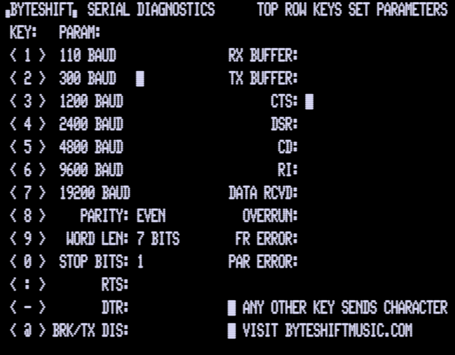
The software is available below in two formats:
I also have available a 35 track SS/SD DMK-format disk image, bootable with NewDOS/80, containing the above diagnostics, and a copy of the ST80D terminal software. You can load this image into an emulator (I recommend the excellent TRS80GP) or use a Greaseweazle or similar device to write the image to a physical floppy for booting your Model I: